1、 Overview of smart grid monitoring system
Smart grid monitoring system is the product of the digital and information age. It has been widely used in high / low voltage power transformation and distribution systems in many fields, such as power grid user side buildings, stadiums, scientific research facilities, airports, transportation, hospitals, electric power and petrochemical industries. For example, with the development of information technology, intelligent building has become an important symbol of urban modernization and informatization. The composition of intelligent building usually has three elements, namely building automation system (BAS), communication automation system (CAS) and office automation system (OAS). Bas is the unity of integrated control and management of the whole system. It is based on computer local area network and is used for equipment operation management, data acquisition and process control. Intelligent power monitoring system is an important part of bas. Through the intelligent power monitoring system, the management level of the whole power transformation and distribution system can be greatly improved, and it is convenient to connect with other bas to form a complete building automation management system. Therefore, intelligent power monitoring system is an essential part of intelligent buildings. It can be said that buildings without intelligent power monitoring are not intelligent buildings.
The intelligent power monitoring system monitors the working status of high-voltage switchgear, low-voltage switchgear, emergency generator set, power transformer and EPS / UPS / ATS. Monitoring is realized by real-time recording of various parameters such as single-phase / three-phase voltage, single-phase / three-phase current, power, power factor, electric degree, frequency and current switching state. When the parameter value exceeds the allowable range, early warning and alarm will be generated, and relevant equipment will be controlled. With less investment, it greatly improves the reliability, safety and automation level of power supply and distribution system.
2、 Structure of system network topology
Intelligent power monitoring system is composed of intelligent measurement and control devices, network equipment and computer equipment. The system can adopt different topologies due to different project scale, different functional performance, different importance and different user investment level. However, no matter what topology is adopted, the hierarchical and distributed design idea of "station control management layer - network communication layer - field equipment layer" is adopted. This layered design conforms to the design and implementation standards of the current communication system, and can relatively complete the monitoring and control function in each layer, that is, it can realize remote monitoring and control, and can not affect the functions of this layer and the next layer in case of upper layer failure.
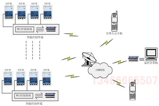
1. Ethernet Remote monitoring flow chart

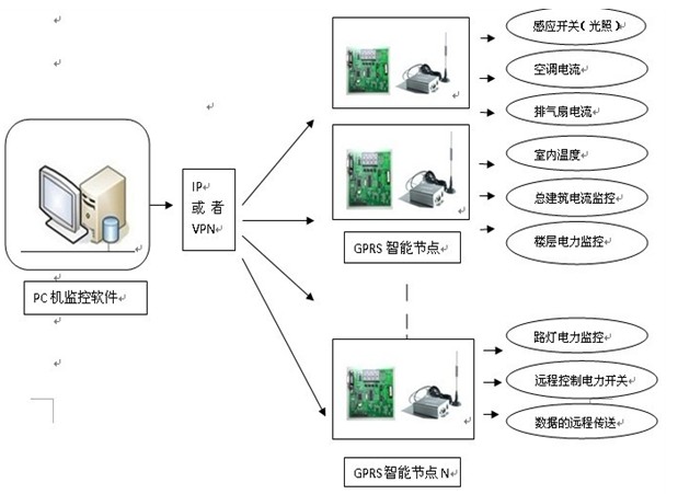
2. Flow chart of remote monitoring through GPRS

3. The specific forms of each structural layer are as follows:
Master station layer (station control management layer):
Located in the monitoring room, including: background host and other related peripherals installed with intelligent power monitoring system. Unpack the data uploaded from the communication Bay, conduct centralized management and analysis, perform relevant operations, and be responsible for the overall monitoring of the whole power transformation and distribution system. The intelligent power monitoring system provides a special communication function module. Through the special Ethernet Hardware communication interface, it sends relevant data and information to the upper level system (such as bas, DCS or dispatching system) in OPC mode or other communication protocols to realize system integration. Real time monitoring and corresponding remote control are carried out through the central computer monitoring software.
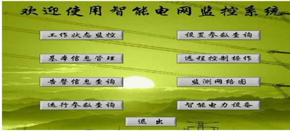
<1> The following is the general operation interface diagram of the software:

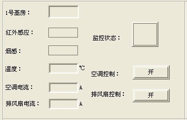
<2> The following are some monitoring interfaces

4. Communication Bay layer (network communication layer):
The communication manager is used to communicate with various devices in the field equipment node layer, collect the data and parameters of various devices, package and transmit them to the master station layer after processing, and act as a transfer unit to receive the instructions issued by the master station layer and forward them to various devices in the field equipment layer. We now use Ethernet Remote and GPRS Remote monitoring module for data acquisition and remote control of each communication node.
Field equipment layer:
It is located at the site of medium and low voltage power transformation and distribution, including: microcomputer protection device, multi-functional instrument, DC screen, temperature and humidity controller, motor protector, current transformer, control electric box, bus communication module, AC contactor and Ethernet access module, serial port extension line, acquisition circuit and other functional modules. It is responsible for collecting all kinds of data and information status of the power field and sending them to the communication Bay. At the same time, it is also used as the execution unit to execute all kinds of instructions issued by the communication Bay.
Current transformer bus module
Ethernet module AC contactor
5. Data acquisition center
<1> Collect data and monitor grid components
Advanced control technology will use smart sensors, smart electronic devices and other analysis tools to measure the system and user parameters and the status of power grid components to evaluate the status of the whole system. These data are quasi real-time data, which is of great significance to master the overall operation status of the power grid, At the same time, the vector measurement unit and the time signal of global positioning system should be used to realize the early warning of power grid.
<2> Analysis data
Quasi real-time data and powerful computer processing ability provide software analysis tools with the ability of rapid expansion and progress. State estimation and emergency analysis will be completed at the second level rather than the minute level, which gives advanced control technology and system operators enough time to respond to emergency problems; Expert system transforms data into information for rapid decision-making; Load forecasting will use these quasi real-time data and improved weather forecasting technology to accurately predict the load; Probabilistic risk analysis will become a routine work to determine the risk level of power grid during equipment maintenance, system pressure and unwanted power supply interruption; Power grid modeling and simulation enable operators to understand the possible scenarios of power grid accurately.
<3> Diagnose and solve problems
The quasi real-time data processed by high-speed computer enables expert diagnosis to determine the solutions of existing, developing and potential problems, and submit them to the system operator for judgment.
<4> Perform automatic control actions
Smart grid makes it possible to perform automatic control actions of problem detection and response through the combination of real-time communication system and advanced analysis technology. It can also reduce the expansion of existing problems, prevent the occurrence of emergency problems, and modify system settings, status and power flow to prevent the occurrence of prediction problems.
<5> Provide information and selection for operators
Advanced control technology not only provides action signals for control devices, but also provides information for operators. The large amount of data collected by the control system is not only useful to itself, but also of great application value to the system operators, and these data assist the operators in making decisions.
6. Control and early warning signal of remote control center
<1> Monitor the switch operation status, protection work and other switching values in real time. Computer real-time display and automatic alarm.
<2> Select the corresponding station number, switch number, closing / opening and other information through the computer screen, feed back the selected switch status on the screen, execute after confirmation, and record the operation time, type, closing / opening number, etc. in real time.
<3> Through the computer, the system voltage, current, active power, reactive power, power factor, over limit alarm and frequency are continuously collected, analyzed, processed, recorded, displayed, and automatically generated reports.
<4> It is used for voltage regulation rise / fall of on load transformer.
<5> It is used to modify the setting value and control word of decentralized relay protection device remotely; And adjust the working state of various instruments.

 Manager Wang
 OfficialAccounts