At present, various automation systems based on distribution network have been improved day by day, and more and more distribution substations, box transformers and switches have realized remote monitoring. However, at present, the functions of various distribution automation systems are mainly to realize the "electrical" monitoring function of primary equipment such as distribution room, ring network cabinet and column switch. Other "non electrical" faults that affect the safe operation of distribution network, such as excessive temperature of cable head, illegal intrusion of personnel, water leakage in equipment room and so on, are not monitored. Many faults are due to the untimely discovery of these small problems, resulting in equipment and power grid accidents, affecting normal production and causing heavy losses to power safety production.
This paper will mainly discuss the establishment of a set of comprehensive monitoring system for the safe operation of distribution substation to realize on-line monitoring of the operation state of distribution network equipment and the factors affecting the safe operation of distribution network, so as to make the distribution network management "controllable" and "under control". So as to completely change the traditional practice of relying on manual inspection and search in the past, effectively prevent faults and improve work efficiency.
1、 Monitoring system structure
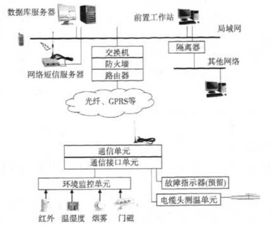
1.1 system structure (Figure 1)

1.2 system composition
The system consists of monitoring unit, communication system and data processing and monitoring center.
(1) Monitoring unit
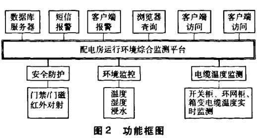
It mainly completes the comprehensive monitoring of the operation environment, safety protection and cable temperature of the distribution room.
(2) Communication system
The communication scheme of the system mainly adopts GPRS communication mode.
(3) Monitoring center
The data processing and forwarding system receives the information data of RTU, and the data processing system analyzes and processes the received information to form fault status information. At the same time, as a sub station, it uploads the fault status to the master station. Complete the monitoring and alarm of the whole fault state. The system can also be connected to the master station that has implemented SCADA system. The application software for the environmental monitoring system is realized by expanding on the SCADA platform (Figure 2).

2、 Functions and features of monitoring system
(1) Real time monitoring function
The short-circuit fault information of the line can be monitored in real time (reserved).
(2) Active alarm function
It can actively report the operation environment data. The alarm information is recorded in the database in real time and can be saved for a long time as needed; Audible and visual alarm can be provided.
(3) Flexible transmission function
Optical fiber, GPRS, carrier, wired and other communication modes are optional, and the system operation does not depend on the selection of communication mode.
(4) Data management function
All system configuration data and alarm information are stored in the database for statistical analysis; Various statistical reports and charts can be generated according to user requirements. According to different topological positions and alarm types of alarms, provide data analysis function to determine fault causes and fault locations.
(5) System management function
The main control unit, acquisition equipment, monitoring points, operators and system functions can be configured; The system log makes detailed records of system status and personnel operation.
(6) Regular reporting of equipment status
The beat mode is adopted to report the equipment status regularly. If the communication fails, it will be regarded as equipment failure.
3、 Monitoring center
(1) System software
The system is a comprehensive monitoring and management software platform, which is completely based on the standard B / S framework. It uses network technology, TCP / IP technology and GPRS communication technology to process the alarm information and various management information from each site. Through the process of analysis, processing and verification, these data ensure that the alarm information can be recorded and analyzed timely and accurately, and provide the maintenance department with the required statistical reports and other analysis data. The system adopts object-oriented technology, around the equipment object, and forms the relevant information into a whole, which can meet the requirements of different applications. Based on the basic equipment model, the hierarchical relationship of equipment is established, which is intuitively reflected in the form of equipment tree.
The system is equipped with a short message alarm server. When the system detects a fault, it will automatically send alarm information to the designated personnel (multiple people at the same time) through the short message server, and record all alarm information. SMS alarm server relies on GSM network to send and receive SMS. It uses a 10base T Ethernet interface is connected to the network; A GSM module is used to send and receive alarm short messages.
The system adopts standard database and provides standard database access interface. Various data and operation logs are recorded in the standard database, which supports the existing EXECL office software to directly generate corresponding reports. It also provides the CAAC with standard development interfaces, which can be easily embedded into the existing MIS system to form complex applications. If users can make web pages, they can generate favorite interfaces according to their hobbies.
(2) Main functions
① Data acquisition and processing;
② Various operation faults are alarmed through SMS;
③ The system adopts open structure and provides secondary development interface.
4、 GPRS networking scheme
The monitoring center adopts APN special line, and all points adopt the networking mode of internal network fixed IP to realize network data transmission. In this scheme, the customer center is connected to the GPRS network of the mobile company through a 2mapn special line, the private fixed IP address is used for wide area connection between the interconnection routers of both parties, and the GRE tunnel is used between GGSN and the interconnection router of the mobile company. Assign a special APN to customers, and ordinary users shall not apply for the APN. The SIM card used for GPRS private network only opens this special APN, and the use of other APNs is limited. After obtaining the APN, assign mobile internal fixed IP to all monitoring points and centers. End to end encryption is adopted between mobile terminal and server platform to avoid possible leakage of information in the whole transmission process. Both parties use firewalls for isolation, and conduct IP address and end El filtering on the firewall. This scheme is the most ideal in terms of real-time, security and stability.
5、 Station end equipment (RTU)
5.1 main functions of RTU in power distribution room
(1) Safety protection subfunction
Access control: confirm the identity and prohibit people without card from entering; Infrared radiation: give an alarm when someone enters the monitoring area.
(2) Environmental monitoring subfunction
It mainly monitors the ambient temperature, humidity and water immersion of equipment operation, and can remotely start and stop air conditioners, fans and other equipment when necessary.
(3) Cable temperature monitoring sub function
It mainly monitors the temperature of the cable head. When it is found that the temperature exceeds the warning value, it will give an alarm immediately to prevent accidents.
5.2 safety protection subsystem
It mainly realizes the safety protection and anti-theft monitoring of the power distribution room, including perimeter protection, access control, etc. Perimeter protection traditionally uses infrared radiation. Access control includes door magnetic detection or intelligent access control system. The intelligent access control system monitors and manages each controller through RTU in the power distribution room.
5.3 environmental monitoring subsystem
The main task of the environmental monitoring subsystem is to monitor the temperature, humidity, water leakage and intrusion of outsiders at each work site. In case of any abnormality, the system will give an alarm automatically, and can automatically start the air conditioner, fan or water pump to dehumidify or pump water to the cable trench. The monitoring quantity of water leakage and smoke detection system mainly includes: infrared detection; Smoke detection; Water immersion test; Access control detection. The data acquisition terminal collects a variety of sensors to monitor various state information in the environment in real time. The ambient temperature and humidity value is detected by the temperature and humidity sensor, and the upper and lower limit alarm of temperature and humidity can also be generated according to the set upper and lower limits; Fire alarm is detected by ion smoke sensor, and ponding information on the ground or cable trench is detected by immersion sensor; The alarm of illegal intrusion is detected by passive infrared detection sensor, photoelectric reflection sensor and door magnetic sensor. Through the monitoring of the above information, the real-time monitoring of safety protection of power distribution room, water inflow of cable trench and smoke detection can be completed.
5.4 cable head temperature monitoring subsystem
The on-line detection subsystem of cable joint temperature is mainly designed for the early warning of cable joints in ring main cabinet and switch cabinet due to insulation aging or poor contact. When the temperature of the cable or cable head rises and exceeds the set alarm limit due to the hidden trouble of the cable, the system will give an alarm. And display the location of the alarm point and record the alarm time, timely and accurately guide the maintenance and fault search, so as to effectively prevent the occurrence and expansion of cable fault.
The system uses "differential comparison method" to judge whether the cable temperature exceeds the limit. That is, a temperature sensing probe is placed at each phase of the cable joint. Through the relative change of the temperature of the three-phase probe in the same circuit, when the relative change exceeds a certain value, it is considered that the temperature of the cable joint is too high, and the alarm process is started immediately to send the information to the monitoring center. Through this scheme, the different temperature alarm limits caused by different line loads and different seasonal temperatures (winter and summer) are solved, and the "fault false alarm" of the system is avoided.
6、 Conclusion
Through the research of this technology and the application of the system, it can greatly save the maintenance cost, improve the accident prevention ability and improve the accident response speed, so as to improve the safe operation level of the whole railway power system and improve the economic benefits of the enterprise.

 Manager Wang
 OfficialAccounts