

Aiming at the problem of real-time communication between electric pitch system and main controller of large wind turbine, a communication system based on RS-485 is designed by using Modbus protocol. The mapping between communication data and Modbus protocol standard function code is analyzed, and the host communication program and slave communication program are given. The experimental results show that the communication network based on Modbus protocol reliably realizes the communication between the master controller (Master) and the three blade servo control systems (slave), and can meet the communication function requirements of the fan blade control system.
1. Introduction
The design and development of wind turbine control system is one of the biggest difficulties in the design and development of wind turbine. The key core control technology mainly includes one of the two core components of main controller and pitch controller. At present, there are two kinds of pitch control systems: hydraulic drive and servo motor drive. Servo motor drive has become the main pitch control drive mode abroad because of its unique advantages. The purpose of pitch controller is to maintain the constant power output of the unit by adjusting the pitch angle of the wind turbine under the condition of high wind speed. The pitch device adopts the hardware system composed of high-precision three closed-loop servo, which has high precision and easy maintenance. At the same time, the appropriate communication protocol is selected to make the main controller work together with the three blade drivers. Modbus protocol is simple, easy to use, cost-effective, high-speed and efficient transmission, and its hardware requirements are simple and economical. Using it to realize the communication between the main controller and the pitch driver can effectively reduce the production cost of the device.
2. Communication network structure and function of pitch controller
The fan local monitoring system (upper computer) communicates with the electric pitch controller in the hub through the fieldbus, and can control the pitch drivers of three blades at the same time. The command value is sent to the pitch driver according to the relevant quantities such as wind speed, generator power and speed. At the same time, the pitch driver (lower computer) can also feed back the state generated by operation to the upper master controller. The upper computer monitoring software is convenient and intuitive, and can clearly read the operation of each blade of the fan.
The lower computer of electric pitch must be able to quickly respond to the command of the main controller. The electric pitch servo system of three blades has the requirements of high-performance synchronization mechanism, safety and reliability, and is independent of each other The lower check-in system can fully meet the requirements of communication speed and reliability. The down busy machine composed of three electric pitch servo controllers has the function of position servo. It adopts the directional operation of rotating in the magnetic field to complete the closed-loop control of position, speed and current. The relevant parameters of the motor are identified before shutdown or formal operation, and the control parameters are set on this basis to reduce the peak value of torque fluctuation caused by gust It can reduce the mechanical stress of the wind turbine and the transition of output power and avoid resonance Before formal operation, the input, output and acquisition channels are controlled, with fully functional debugging software, possible parameter setting to avoid resonance, emergency safety chain and real-time communication function. Figure 1 shows the structural block diagram of the communication network of the whole electric pitch controller.
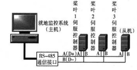
Fig. 1 communication network structure block diagram of electric pitch system
3. Application of Modbus Protocol in the communication of pitch changing system
3.1 mmhus communication principle
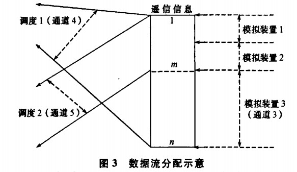
Modbus is a simple "client server" H protocol Its essence is the main small mode, but the host is the client The slave is the server. Its Tongqian follows the process of "R": ① the client prepares the request and sends the request to the server; ② The server analyzes and processes client requests Then send the result to the client; ③ If anything goes wrong The server will return an exception function code The communication process under error free and abnormal response is shown in Fig. 2 and Fig. 3 respectively.
3.2 the mapping vehicle system of communication data and standard function code of Modbus protocol adopts the I / TU mode of mmbus protocol for transmission, and adopts the ^ computer interface and monitoring module written by VC + + in the system Medium is the host The pitch servo controller module acts as a slave The communication data to be processed by the host is the data sent to the lower computer under the host and the data uploaded from the host to the upper computer The data sent includes the setting of system data (modifying the blade change angle and blade running speed), the commands made to the pitch controller (power on, start, stop, emergency stop and power off), and the commands to modify the action of components in the pitch cabinet (brake, main power supply, backup power supply, safety chain closing, heat dissipation, heating and enabling), The data uploaded to the mobile phone include unit parameters (DC bus voltage, motor temperature, braking state, current sensor), blade data (current blade angle, current blade running speed, redundant encoder angle) Safety chain status (90 degree limit switch, 0 degree limit switch, safety chain normally closed), fan operation mode (shutdown mode, full machine mode, automatic mode, manual mode), shutdown status (normal shutdown, emergency shutdown), pitch cabinet status (temperature, power supply, heating), fault information (obstacle ID number, fault name), normal communication signal and blade synchronization. All data (bits and registers) processed by MODBUS are placed in the device application memory; There are many ways to realize the data organization in the equipment. The organization mode adopted by the system makes the data blocks independent. Since the data in different blocks are not related, independent data blocks can be accessed by using different MODBUS function commands. The phase module of pitch controller communication data is mapped with the standard function code defined by Modbus protocol, as shown in table I.
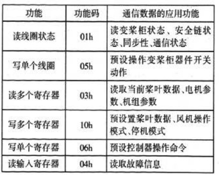
Table 1: mapping table of standard function codes defined by communication data application and Modbus Protocol
The following describes the query and response process of the whole fan communication by querying the blade fault information. In the pitch system of this design, there is one master and three blades, so there are three slaves with addresses of 01h, 02h and 03h respectively. Now take slave 1 with address 01h as an example. The format of host query command request query frame is shown in Table 2.
Table 2 format of sending command frame
Slave address function code starting address input CRC check code
01h 04h 0008h 0001h A17h
The function of this command is to read the fault information of blade L, that is, to read the value of register 30009 from slave 01h. The corresponding data frame format of blade 1 is shown in Table 3.
Table 3 format of response frame
Slave address function code starting address input CRC check code
01h 04h 02h 0011h 1F6CH
The meaning of this corresponding frame is: the data value in register 30009 is "0x0011", which means that blade 1 has No. 17 fault (information transmission timeout fault), the host will respond to the fault, and all blades will follow the propeller to the safe stop position (880). The CRC check code is "1f6ch".
3-3 communication process and analysis
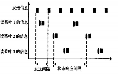
In the whole communication process, the man-machine interface and monitoring module are the host, receive the feedback information of three blades (slave) in turn, and continuously send commands to query the status information of three blades. As a slave, the servo controller of the blade is ready to respond to the command sent from the host and execute the relevant instructions such as pitch. In order to improve the real-time performance of communication, the system adopts interrupt mode to receive and send frames. The composition of communication program is mainly divided into initialization, interrupt receiving module, frame processing module, CRC verification module, register refresh module and communication control module. The communication baud rate is 19200bit / s. The servo driver of the three blades will receive the command from the upper computer at the same time. In the interval when the host sends the blade information, the three blades will respond to the host in turn. The interval between the main engine sending blade information is 40ms. The response time interval of the three blades is 120ms. The communication sequence is shown in Figure 4.
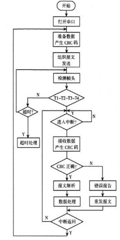
Fig. 4 communication sequence analysis diagram
3.3.1 host communication program design
The host communication program adopts the development environment based on multi task and visual windows operating system, the development tool is Visual C + + 6.0, and the MSComm ActiveX control is used to send and receive data through the communication port. The communication process of the host is as follows: open the serial port, start preparing the data to be sent, run the CRC generation subroutine, and obtain the CRC check code of the data to be sent; Run and organize the message frame command to form a complete frame in the form of Modbus RTU
Send the formed message; After the transmission is completed, enter the stage of receiving the frame. Detect the frame header (t1-t2-t3-t4). After judgment, if it meets the waiting time of four characters, enter the process of waiting for receiving interruption. In case of interrupt response, enter the interrupt service subroutine to receive the sent message data and perform CRC verification; If the received command meets the requirements, the host starts to enter the frame analysis stage, completes the communication data analysis according to the pitch communication protocol, and completes the relevant display and command sending functions. Enter the main program after processing, otherwise, report the communication error, and then resend the message. After sending, enter the main program and enter the data preparation stage; If the interrupt response times out, the program will conduct timeout processing, return to the main program after processing, and re-enter the data preparation stage. The communication flow of the host is shown in Figure 5.
3.3.2 slave communication program design
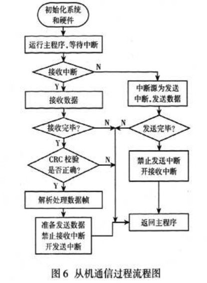
The development environment of slave program is Ccs3 3。 The communication program of the slave mainly completes the data frame reception and CRC verification, and responds to the response of the host to perform the corresponding tasks. At the beginning, the slave program enters the receiving interrupt program, and the interrupt module starts to receive the command data frame sent by the host. Only after a complete frame is read, the slave starts to process the command sent by the host. In the slave message processing module, firstly, the processing module starts to match the frame header, calls the CRC verification module to calculate the request frame, and the calculation result
Figure 5 host communication flow chart
Compare with the received CRC value, if the CRC check is wrong Then exit the processing frame module and discard the current frame. This indicates that the frame received by the slave is invalid + the slave continues to wait for the query of the host. Only when the inquiry message sent by the Feng machine passes the CRC calibration, the slave machine will carry out the next step of processing according to the pitch pitch and prepare to form a response frame. The content package of the response frame contains the information required by the ancient host. meanwhile. The slave calls the CRC verification subroutine again Verify the response data The result is attached to the response content to form a complete frame, so as to facilitate the data inspection of subject B. At the same time, the slave (pitch servo controller) will execute the corresponding pitch command. After the response frame is completed, the slave prohibits receiving interrupts and enables sending interrupts When the slave data is sent, the slave can receive the interrupt to prepare for the next attack to receive the query command from the host again The slave communication program is shown in Figure 6
On the ground experimental platform of the pitch system, turn on the fan local monitoring software (t machine) and turn it on! Connect the two pitch device covers Run the pitch program. At this time, the blade operates in automatic mode The angle value of pitch is set to 70 degrees. When the system is running, the blade speed is 7.5 degrees / s. The feedback information of the lower computer is normal, the safety chain is closed and the brake is opened. The blade synchronization is good.
4. Concluding remarks
Because Modbus protocol has the characteristics of standardization, simplicity, high efficiency and good openness, it has become one of the field bus discussions that should be cut widely before 14. Through the analysis of the system operation experiment, the conclusion shows that the wind power pitch system device adopts MODB S protocol Reliably realize the mutual communication between the local monitoring system (host) of fan Ding and three blade control systems (slave), with friendly human-computer interaction, low communication error rate and strong anti-interference ability. It can fully meet the communication function requirements of fan blade control system and can be well popularized.

 销售王经理
销售王经理
 微信公众号
微信公众号